Bandpass Filter Design Matlab
This filter is one of the passive harmonic filters types. If Wn is the two-element vector w1 w2 where w1 w2 then butter designs a bandpass or bandstop filter with lower cutoff frequency w1 and higher cutoff frequency w2.
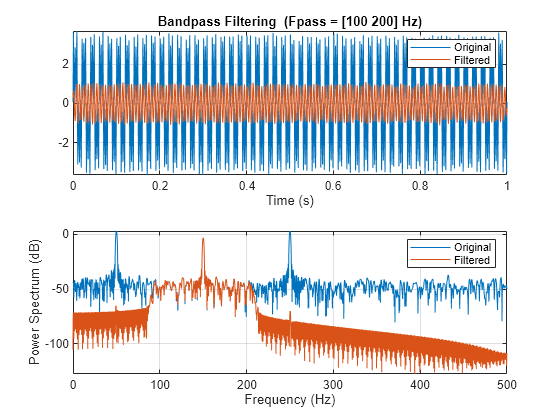
Bandpass Filter Signals Matlab Bandpass
Matlab fir2 function uses frequency sampling method.
. If Wn is scalar then butter designs a lowpass or highpass filter with cutoff frequency Wn. This MATLAB function filters the input signal x using a bandpass filter with a passband frequency range specified by the two-element vector wpass and expressed in normalized units of π radsample. Data with high dynamic range is displayed with perceptually boosted local contrast.
This is a double-tuned type harmonic filter that can be designed with a single resistor two capacitors two inductors. Use the state-space representation. Using Matlab you can implement and design different algorithms.
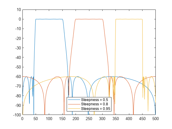
The accuracy of the frequency response is determined by the specification method defiend below. One goal of those short utility functions is to allow you to leave all your. Any function with this prefix is simply a wrapper looping over all individuals in the cohort.
Frequency response tells the output magnitude for each frequency or gain for unit input for each frequency. If Wn is the two-element vector w1 w2 where w1 w2 then butter designs a bandpass or bandstop filter with lower cutoff frequency w1 and higher cutoff frequency w2. This means you should not use analogTrue in the call to butter and you should use scipysignalfreqz not freqs to generate the frequency response.
Performing group-level microstate analysis. This filter is mainly used for harmonic filtration purposes with high order. Design a 20th-order elliptic bandpass filter with a lower passband frequency of 500 Hz and a higher passband frequency of 560 Hz.
The type of filter designed depends on cut off frequency and on Ftype argument. For example calling coh cohind_preprocess_filter130 is equivalent to running a for loop through all individuals in the cohort and using the preprocess_filter function to bandpass filter 1-30 Hz. You are working with regularly sampled data so you want a digital filter not an analog filter.
The circuit diagram of the bandpass harmonic filter circuit is shown below. If the signal is not long enough compute the minimum. If Wn is scalar then butter designs a lowpass or highpass filter with cutoff frequency Wn.
For digital filters the cutoff frequencies must lie between 0 and 1 where 1 corresponds to the Nyquist ratehalf the. This is a lowpass filter with a normalized cut off frequency of F. Buttern F Ftype is used to design any of the highpass lowpass bandpass bandstop Butterworth filter.
Using the OctaveMatlab code below we can see how to design a lowpass filter with a bandwidth of 10kHz and a cutoff of 15kHz using Octaves built in fir1 function which is well documented here. Designing an FIR filter length to be odd length will give the filter an integral delay of N-12. Next we explain the properties of polyphase filters ie they have all-pass gain and possible different phases.
Online Filter Design Tool. CLAHE parameters are relative to display pixels and therefore will not result in an effective bandpass when zooming out largely on statically pre-processed images. For digital filters the cutoff frequencies must lie between 0 and 1 where 1 corresponds to the Nyquist ratehalf the.
You can load data from different sources such as files databases or the web to analyze your data and visualize it using Matlab visualization application which gives you a wide range of graph plots to choose from. Design an identical filter using designfilt. Signal is at least twice as long as the required filter order design and use that filter.
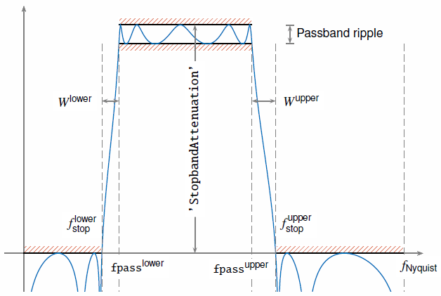
Specify a passband ripple of 3 dB a stopband attenuation of 40 dB and a sample rate of 1500 Hz. The phase delay gives the time delay in seconds experienced by each sinusoidal component of the input signal. Effect of the CLAHE live filter in TrakEM2.
For example in the simplest lowpass filter of Chapter 1 we found that the phase response was which corresponds to a phase delay or one-half sampleThus we can say precisely that the filter exhibits half a sample of time delay at every frequency. Highpass Bandpass Bandstop Arbitrary. Each polyphase filter ρ k n operating at the original sampling rate f s assuming 8 kHz is a downsampled version of the interpolation filter hn operating at the upsampling rate Lf s 32 kHz assuming an interpolation factor of L 4.
The Nyquist frequency is half the sampling rate.
Bandpass Filter Signals Matlab Bandpass
Bandpass Filter Signals Matlab Bandpass
Rf Filter Design Matlab Simulink

Bandpass Filter From High Pass And Low Pass Filter Matlab Youtube
No comments for "Bandpass Filter Design Matlab"
Post a Comment